
Lattice Boltzmann Simulation of Heat Transfer in a Square Cavity Coupled with Copper–Graphene Nanocomposite Wall
Abstract
A numerical investigation is performed to study conjugate natural convection heat transfer in a square cavity coupled with a Copper–graphene nanocomposite solid wall. The cavity is filled with a Newtonian fluid and subjected to a constant heat flux applied over a finite portion of the bottom wall. At the same time, the vertical sidewalls are maintained at a constant cold temperature, and the remaining boundaries are adiabatic. Heat conduction in the solid wall and convection in the fluid domain are simultaneously considered. The Lattice Boltzmann Method (LBM) with the Bhatnagar–Gross–Krook (BGK) collision model is employed to solve the governing equations. The effective thermal conductivity of the Copper–graphene nanocomposite is evaluated using a micromechanical model accounting for graphene nanoplatelet waviness, alignment, and Interfacial Thermal Resistance (ITR). The numerical model is validated against well-established experimental correlations for natural convection, showing excellent agreement. Parametric analyses are conducted to examine the effects of Rayleigh number, constant heat flux length, and solid wall thickness on flow structure and heat transfer characteristics. The results indicate that the Copper–graphene nanocomposite significantly enhances heat transfer compared to pure Copper by reducing surface temperature and increasing local and average Nusselt numbers. Increasing Rayleigh number intensifies buoyancy-driven convection, while larger heat flux lengths reduce heat transfer efficiency. Thicker nanocomposite walls improve conductive heat spreading and overall thermal performance.
Keywords:Conjugate heat transferNatural convectionCopper–graphene nanocompositeLattice Boltzmann methodConstant heat flux
1. Introduction
Natural convection heat transfer plays a crucial role in many engineering applications, including furnaces, electronic component cooling, heat exchangers, building heating and cooling systems, and solar energy technologies. Owing to the wide applicability of free convection, numerical simulation of natural convection in different geometrical configurations has attracted significant attention from researchers. A substantial portion of previous studies has focused on two-dimensional enclosures with smooth walls subjected to isothermal boundary conditions [1–3].
The inherently low thermal conductivity of conventional base fluids such as water, oils, and ethylene glycol is one of the main factors limiting the thermal efficiency of heat transfer systems. To overcome this limitation, the suspension of solid particles with high thermal conductivity in base fluids has been proposed. With advances in nanotechnology, Choi [4] introduced the concept of nanofluids by dispersing nanoparticles, typically smaller than 100 nm, into base fluids.
Extensive analytical, experimental, and numerical investigations have been conducted on natural convection of nanofluids in two-dimensional enclosures. Kim et al. [5] analytically studied the instability of Rayleigh– Bénard natural convection in nanofluids under isothermal wall conditions. They reported an enhancement in heat transfer due to the presence of nanoparticles. In contrast, Wen and Ding [6], through experimental analysis of a water–TiO₂ nanofluid, observed a deterioration in heat transfer performance with increasing nanoparticle concentration. From a numerical standpoint, studies by Khanafer et al. [7] and Aminossadati and Ghasemi [8] investigated water–CuO nanofluids in square cavities with isothermal walls and demonstrated that the average Nusselt number increases with nanoparticle volume fraction over the investigated Rayleigh number1 range.
The discrepancies observed in the literature indicate that the enhancement or deterioration of natural convection heat transfer in nanofluids is strongly dependent on the models employed for effective viscosity and thermal conductivity. Several studies [9–11] have shown that the selection of thermophysical property models can significantly influence the predicted Nusselt number. Moreover, it has been widely reported that Brownian motion plays a key role in determining the effective thermal conductivity and viscosity of nanofluids, thereby exerting a significant impact on natural convection heat transfer behavior.
Natural convection of electrically conducting fluids under the influence of a magnetic field, known as Magnetohydrodynamic (MHD) flow, has also been extensively studied due to its relevance in engineering applications such as geothermal energy extraction, crystal growth processes, nuclear reactor cooling, polymer processing, and metallurgical industries [12]. Numerical simulations of MHD natural convection of nanofluids have been performed using various numerical techniques, including finite difference, finite element, and Lattice Boltzmann Methods (LBMs)2.
In recent years, the LBM has gained considerable popularity owing to its explicit formulation, ease of implementation of complex boundary conditions, and inherent suitability for parallel computation [13–15]. These advantages have made LBM a powerful tool for simulating flow and heat transfer in complex systems, such as porous media, multiphase flows, and multicomponent flows [16], [17]. Studies on MHD natural convection of nanofluids in enclosures can generally be classified into three categories: 1) enclosures with smooth walls and uniform temperature distributions, 2) enclosures with curved walls and uniform temperature distributions, and 3) enclosures with smooth walls and non-uniform wall temperature distributions.
Ghasemi et al. [18] investigated MHD natural convection of nanofluids in square cavities with isothermal walls and reported that heat transfer characteristics are strongly dependent on the Rayleigh and Hartmann numbers. In addition, due to the practical relevance of non-smooth boundaries in thermal systems such as solar collectors, heat exchangers, and electronic devices, several researchers have examined natural convection in enclosures with wavy or curved walls [19–21]. Their results demonstrated that boundary geometry significantly influences flow structure and heat transfer rates.
Furthermore, the effects of internal obstacles, rigid and flexible fins, and moving boundaries on natural convection in enclosures have been widely investigated. These studies revealed that the geometry, location,
1 The Rayleigh number is identified as the key.
2 The Lattice Boltzmann Method (LBM) is employed to accurately simulate coupled fluid flow and heat conduction in solid–fluid domains.
and thermophysical properties of such internal components can either enhance or suppress heat transfer, depending on the flow configuration and operating conditions [22–30].
2. Problem Definition
In the present study, a comprehensive numerical investigation is performed to analyze the phenomenon of conjugate heat transfer.1, which encompasses the interaction between combined convection inside a square cavity and thermal conduction through a Copper–graphene nanocomposite wall2. Fig .1 shows the computational domain. The right and left sidewalls are maintained at a constant cold temperature, while the bottom wall contains a centrally located heat source of length (L), subjected to a uniform heat flux. The remaining sections of the bottom wall and the top wall are considered adiabatic boundary conditions. A solid layer of Copper–graphene nanocomposite with a thickness (h) is attached to the bottom wall, enabling simultaneous heat conduction within the solid region and convective heat transfer in the fluid domain above.
This figure is shown in the PDF version of the article.
2.1 Thermophysical Properties of Copper–Graphene Nanocomposites (Solid Phase)
The rapid increase in heat generation within microelectronic devices, driven by the continuous miniaturization and higher integration density of semiconductor circuits, has made thermal management a critical design challenge. Excessive heat accumulation can significantly reduce the operational lifetime and reliability of electronic components. Consequently, efficient heat dissipation has become a key requirement in the development of advanced microelectronic systems, highlighting the necessity for packaging materials with superior thermal properties [26], [27].
Thermal conductivity plays a decisive role in the selection of optimal materials for thermal management applications. Owing to the exceptional intrinsic thermal conductivity of graphene, copper-based metal matrix composites reinforced with silicon Carbide and Graphene Nanoplatelets (GNPs) are considered among the most promising candidates for electronic packaging and heat-sink applications. These materials can effectively function as thermal terminals to dissipate accumulated heat. To the best of the authors’ knowledge, comprehensive studies focusing on the thermal conductivity of copper-based metal matrix composites reinforced with discontinuous SiC/GNPs remain limited. In particular, the influence of GNP microstructural characteristics on the axial and transverse thermal conductivity of such composites is not yet fully understood.
1 A conjugate heat transfer model is developed for natural convection in a square cavity coupled with a copper–graphene nanocomposite wall. 2 Copper–graphene nanocomposite walls considerably enhance heat transfer performance and reduce maximum surface temperature compared to pure Copper.
The macroscopic thermal performance of graphene-reinforced composites is strongly affected by the volume fraction, geometric characteristics, and spatial distribution of graphene fillers, as well as by the Interfacial Thermal Resistance (ITR) between the nanoparticles and the metallic matrix [28]. Experimental characterization of the thermal properties of GNP- and SiC-reinforced metal matrix composites is often complex, time-consuming, and costly. Therefore, micromechanical modeling approaches have been widely developed to predict the effective thermal conductivity of composite systems [29], [30].
Among these approaches, the Effective Medium Approximation (EMA) has been extensively employed for predicting the thermal conductivity of graphene-filled composites [31], [32]. Accurate modeling requires careful consideration of the reinforcement volume fraction, geometric parameters, and intrinsic properties of the composite constituents. ITR plays a crucial role in governing heat conduction behavior in such materials. Based on the effective medium theory [33], the in-plane and through-plane thermal conductivities of GNP-reinforced composites can be expressed as:
2 + VgβIP(1 + 〈cos2 θ〉) 1 + VgβIP(1 − 〈cos2 θ〉)
KIP = Km 2 , KTP = Km 2 , (1)
2 − VgβTP(1 − 〈cos θ〉) 1 − VgβTP〈cos θ〉 where Km denotes the thermal conductivity of the matrix, Vg represents the volume fraction of graphene nanoplatelets, and ⟨cos2θ⟩ characterizes the degree of GNP alignment within the metallic matrix. A value of ⟨cos2θ⟩ =1/3 corresponds to a randomly oriented distribution of GNPs.
The parameters βIP and βTP are defined as:
RkKg K Km ( t + 1)
βIP = − 1, βTP = 1 − , (2)
RkKg Kg Km ( + 1)
where Kg,l, and t denote the thermal conductivity, length, and thickness of the graphene nanoplatelets, respectively, and Rk is the ITR between graphene and the matrix.
Microstructural analyses have revealed that graphene nanoplatelets in metal matrix composites are often wrinkled or corrugated [34–36], primarily due to their low bending stiffness and fabrication processes. As a result, investigating the influence of GNP waviness on the effective thermal conductivity of graphene-filled composites is of critical importance.
One of the major challenges in synthesizing graphene–metal nanocomposites lies in achieving a uniform dispersion of nanoparticles and a homogeneous microstructure [37]. Due to van der Waals forces and entanglement effects, graphene nanoplatelets exhibit a strong tendency to agglomerate within the metallic matrix [38]. To mitigate this issue, multi-step dispersion techniques have been proposed to reduce GNP agglomeration and improve composite homogeneity [39], [40]. The density of Copper–graphene nanocomposites can subsequently be evaluated using the volume fraction concept.
To determine the thermal conductivity of the copper–graphene nanocomposite, the results reported by Ramanathan et al. [41] were employed, as illustrated in Fig. 2. This figure compares the thermal conductivity of GNP/copper composites. The thermal conductivity of the copper matrix is considered as Km=350 W/mK [42]. The length and thickness of the graphene nanoplatelets are l=25 μm and t=12 nm, respectively. The thermal conductivity of graphene varies between 1000 and 5300 W/mK, depending on factors such as defects and thickness [42]. In all calculations, an average value of Kng≈3000 W was selected. Micromechanical modeling was performed under various conditions to investigate the effects of GNP wrinkling and graphene/copper ITR on the composite thermal conductivity. The in-plane thermal conductivity KIP and through-plane thermal conductivity (KTP) of copper composites filled with GNPs are presented as functions of the GNP volume fraction. A good agreement is observed between experimental data [43–46] and the predictions of Hassanzadeh-Aghdam and Mahmoodi et al. [47] when considering ITR and wrinkled GNPs. Therefore, including graphene/matrix ITR and GNP waviness in micromechanical models is essential to achieve accurate predictions in comparison with experimental results.
In the present study, the graphene/matrix ITR and the waviness of GNPs are incorporated into the model, and a GNP volume fraction of 15% is assumed (Table 1) [47].
This figure is shown in the PDF version of the article.
Table 1. Thermophysical properties of Copper and GNP [47].
This table is shown in the PDF version of the article.
3. Governing Equations
In this study, conjugate heat transfer is considered. The fluid is assumed to be two-dimensional, steady, incompressible, and laminar. The temperature variations of the physical properties of the fluid and solid are neglected. There is a regional thermal equilibrium between the fluid and the solid. The governing equations for flow and heat transfer are expressed as:
Continuity equation:
∇. u = 0, (3)
Momentum equation:
∂you
ρf + ρfu. ∇(u) = −∇(p) + ∇. (μp∇u) + ρfgβ(T − Tref), (4) Energy equation for fluid:
∂T 2
(ρCp)f ( + u. ∇T) = Kf∇ T, (5)
Energy equation for a solid:
∂T 2
(ρCp)s ( ) = Ks∇ T, (6)
where subscript f represents fluid and s represents solid, you is the velocity vector. T is temperature, ρ is the density, K is the thermal conductivity, cp is the specific heat capacity, p is the pressure, g is the gravitational acceleration, β is the thermal expansion coefficient, and Tref is the reference temperature.
3.1 Lattice Boltzmann Method
The LBM is a powerful numerical method for modeling particle dynamics by considering distribution functions that capture particle interactions. In this study, the LBM is applied, Using the Bhatnagar–Gross– Krook (BGK) approximation for the collision operator, the discrete hydrodynamic and thermal lattice Boltzmann equations for axisymmetric flows are expressed as follows:
fα(X + eαδt, t + δt) − fα(X, t) = −ωf[fα(X, t) − fα eq(X, t)] + rho(i, j)F (i, j), (7) gα(X + eαδt, t + δt) − gα(X, t) = −ωg[gα(X, t) − geq α (X, t)], (8)
where X = (x,y) is the particle position, f and g are the Momentum and thermal distribution functions, respectively, and feq and geq are the corresponding equilibrium distribution functions. eα represents the microscopic lattice velocities. The indices i and j denote the coordinate directions along the axial and radial axes. δt is the time step, and eα is the ith component of eα. The collision frequency is ωf=1/τf, where τf is the relaxation time in the Momentum equation. The body force term F(i,j) is calculated as:
F(i, j) = 3ω(k)gxβθex + 3ω(k)gyβθey, (9)
where θ is the dimensionless temperature, defined by:
T − Tc
θ = " . (10)
q W⁄Ks The discrete velocity vectors in the LBM for the D2Q9 model are given by:
(0,0), α = 0,
(α−1)π (α−1)π
eα = e (cos 2 , sin 2 ) , α = 1,2,3,4, (11)
π π π π
{√2e (cos [(α − 5) + ] , sin [(α − 5) + ]) , α = 5,6,7,8,
2 4 2 4
where cs = e⁄√3 (e = δx⁄δt) is the lattice speed. The weighting factors w for the equilibrium distribution function in different directions are:
w0 = .
wα = , α = 1,2,3,4. (12)
wα = 36 , α = 5,6,7,8.
Macroscopic hydrodynamic and thermal variables are obtained as:
ρ = ∑α fα. (13)
ui = ρ ∑ eαifα. (14)
θ = ∑ gα. (15)
3.2 Boundary Conditions
The square cavity has four solid walls, where the no-slip condition is imposed using the bounce-back scheme. Thermal boundary conditions are applied using a second-order accurate approach. Left and right walls are maintained at θ=0 with unknown distribution functions set to their equilibrium values consistent with the wall temperature:
g(1,0, j) = −g(3,0, j).
g(5,0, j) = −g(7,0, j). (16)
g(8,0, j) = −g(6,0, j).
g(6, n, j) = −g(8, n, j).
g(3, n, j) = −g(1, n, j). (17)
g(7, n, j) = −g(5, n, j).
Adiabatic top wall: no heat flux is imposed by copying the thermal distribution functions from adjacent interior nodes:
g(8, i, m) = g(8, i, m − 1).
g(7, i, m) = g(7, i, m − 1).
g(6, i, m) = g(6, i, m − 1).
g(5, i, m) = g(5, i, m − 1).
g(4, i, m) = g(4, i, m − 1). (18)
g(3, i, m) = g(3, i, m − 1).
g(2, i, m) = g(2, i, m − 1).
g(1, i, m) = g(1, i, m − 1).
g(0, i, m) = g(0, i, m − 1).
When a section of length L on the bottom wall is subjected to a uniform heat flux, the fluid temperature at the wall can be determined using Fourier’s law, expressed in dimensionless form:
kS ∂y| = q"w. (19)
By non-dimensionalizing and discretizing the above equation, the dimensionless temperature on the wall can be obtained as:
θ0 = θ1 + ∆R, (20)
where ΔR is the dimensionless spatial step in the LBM grid, and θ1 is the temperature of the bottom wall. Unknown distributions are updated accordingly:
g(2, i, 0) = g(2, i, 0) + .
g(5, i, 0) = g(5, i, 0) + . (21)
g(6, i, 0) = g(6, i, 0) + .
At the remaining portions of the bottom boundary, insulated (adiabatic) conditions are applied, where zero heat flux is imposed. The unknown thermal distribution functions are
g(7, i, 0) = g(7, i, 0).
g(6, i, 0) = g(6, i, 0).
g(5, i, 0) = g(5, i, 0).
g(4, i, 0) = g(4, i, 0).
(22)
g(3, i, 0) = g(3, i, 0).
g(2, i, 0) = g(2, i, 0).
g(1, i, 0) = g(1, i, 0).
g(0, i, 0) = g(0, i, 0).
For the evaluation of heat transfer, the Nusselt number is employed, representing the ratio of convective to conductive heat transfer. When the outer wall is adiabatic, the Nusselt number on the inner wall is defined under steady-state conditions. The local heat transfer coefficient at a given point on the heat source surface is defined as:
hx = , (23)
[Ts(x) − Tc] where Ts(x) is the local surface temperature. Accordingly, the local Nusselt number can be expressed as:
hW 1
Nu(x) = = . (24)
ks θS
The average Nusselt number along the wall is obtained by integration over the cavity length:
∫0 Nu(x)dx
Num = . (25)
4. Result and Discussion
4.1 Grid Independence
To ensure numerical accuracy and eliminate mesh dependency, a systematic grid refinement study was conducted for a horizontal square cavity with an aspect ratio of (A = 1), (ε = 0.4), and Rayleigh number (Ra = 105). Fig. 3 presents the convergence behavior of the average Nusselt number evaluated at the heated wall for successive mesh resolutions.
The results demonstrate that a mesh size of (150 × 180) is sufficient to achieve grid-independent solutions, as further mesh refinement produces only negligible changes in the predicted average Nusselt number. Accordingly, this mesh configuration is employed for all subsequent simulations corresponding to (A = 1). For cavities with larger aspect ratios (A > 1), additional grid points are allocated in the vertical (y) direction to resolve the elongated geometry adequately. In contrast, the number of grid points in the horizontal (x) direction is fixed at 150.
This figure is shown in the PDF version of the article.
4.2 Validation of the Numerical Model
Due to the lack of experimental data matching the exact cavity configuration and boundary conditions of the present study, direct validation is not feasible. Therefore, an indirect validation is performed by comparing the numerical results with the experimental correlation reported by ElSherbiny et al. [48] for natural convection in vertical rectangular cavities. A vertical cavity with an aspect ratio of 5 is simulated, and the predicted average Nusselt numbers for different Ra are compared with the corresponding correlation for Ra < 108. As shown in Fig. 4, excellent agreement is achieved, with a maximum deviation below 4%, confirming the accuracy and reliability of the present numerical model.
This figure is shown in the PDF version of the article.
4.3 Effect of Copper–Graphene Nanocomposite Solid Surface on Heat Transfer
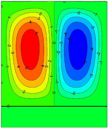
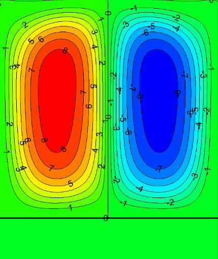
Fig. 5 illustrates the streamlines at Ra=105 and ε=0.8 for the Copper–graphene nanocomposite solid surface and the pure copper surface. In both cases, the flow ascends along the vertical axis of symmetry. It is blocked by the upper adiabatic wall, forcing the fluid to move horizontally toward the isothermal cold sidewalls. The flow then descends along the sidewalls and, after impinging on the bottom wall, returns horizontally toward the central region. A stagnation point is clearly observed at the midpoint of the lower heated surface.
The corresponding isotherm contours at Ra=105 and ε=0.8 are shown in Fig. 6 for both solid surfaces. The isotherms are symmetric with respect to the vertical mid-plane and become increasingly clustered near the heated surface, indicating the presence of a strong temperature gradient. Higher temperatures are observed within the solid region, with maximum concentration near the constant heat flux boundary. A noticeable change in the temperature gradient occurs at the solid–fluid interface, accompanied by a temperature reduction in the fluid region.
A comparison between the Copper–graphene nanocomposite and pure copper surfaces reveals that the enhanced thermal conductivity of the nanocomposite leads to higher heat transfer rates. Under the imposed constant heat flux condition, the higher conductivity results in a lower solid surface temperature.
The variation of the local Nusselt number along the heated surface for both solid materials at Ra=105 and ε=0.8 exhibits a symmetric distribution, consistent with the geometric symmetry and boundary conditions. The streamline patterns indicate that natural convection is relatively weak in the upper regions of the cavity, while the heat transfer process is predominantly confined to the lower part. The local Nusselt number attains its minimum value at the center of the heated surface due to the presence of the stagnation point, where convective heat transfer is weakest. Overall, the Copper–graphene nanocomposite surface yields higher local Nusselt numbers compared to pure Copper, owing to its superior thermal conductivity and reduced surface
This figure is shown in the PDF version of the article.
This figure is shown in the PDF version of the article.
This figure is shown in the PDF version of the article.
4.4 Effect of the Rayleigh Number
The influence of the Rayleigh number on flow structure and heat transfer is examined in a horizontal cavity with an aspect ratio of 1 for a representative porosity of ε= 0.4. Streamline and temperature contours are shown in Figs. 8 and 9 reveal the formation of two symmetric counter-rotating vortices for all Rayleigh numbers considered. At low Rayleigh numbers (Ra =5*103), buoyancy effects are weak, and heat transfer is diffusion-dominated, as indicated by low stream function magnitudes and weakly distorted isotherms. With increasing Rayleigh number, buoyancy-driven convection intensifies, causing the vortex cores to shift upward and the isotherms to become highly distorted, signifying a transition to convection-dominated heat transfer. This behavior is consistent with previously reported observations for similar cavity configurations. At the same time, the present results further demonstrate the role of the copper–graphene nanocomposite surface in enhancing thermal transport under strong buoyancy conditions.
This figure is shown in the PDF version of the article.
This figure is shown in the PDF version of the article.
The local Nusselt number distributions along the heated surface (Fig. 10) exhibit symmetric profiles due to geometric and thermal symmetry. An increase in the Rayleigh number leads to a pronounced enhancement in local heat transfer rates, reflected by higher Nusselt numbers along the surface.
This figure is shown in the PDF version of the article.
4.5 Effect of the Constant Heat Flux Length on Heat Transfer
One of the key differences between isothermal and constant heat flux boundary conditions is the non-uniform surface temperature associated with the latter, leading to the occurrence of a maximum surface temperature. In thermal management applications, particularly electronic cooling, the maximum surface temperature is a critical parameter, as excessive temperatures may cause component failure. Therefore, examining the influence of the length of the constant heat flux region on heat transfer characteristics is of practical importance.
Figures 11 and 12 present the streamline and temperature contours for different ratios of the constant heat flux length.1 to cavity width (ε=L/W=0.2-0.8) at Ra=105 for the copper–graphene nanocomposite surface. As ε increases, a larger portion of the bottom wall is subjected to heat input, resulting in higher energy transfer into the cavity. Consequently, the stream function magnitude increases, indicating intensified buoyancy-driven convection. Simultaneously, the maximum temperature within the solid surface and the cavity increases due to the expanded heat input area.
It is observed that the maximum temperature consistently occurs at the center of the heated solid surface and corresponds to the stagnation point at the midpoint of the lower cavity wall, where convective heat removal is weakest.
1 Constant heat flux length is identified as key.
This figure is shown in the PDF version of the article.
This figure is shown in the PDF version of the article.
The distributions of the local and average Nusselt numbers for different heat flux lengths are shown in Figs. 13 and 14, respectively. Increasing the heat flux length leads to higher surface and cavity temperatures, resulting in a reduction of both local and average Nusselt numbers. The minimum local Nusselt number is observed at the center of the heated surface for ε=0.8, coinciding with the location of maximum temperature and flow stagnation.
This figure is shown in the PDF version of the article.
4.6 Effect of the Copper–Graphene Nanocomposite Solid Thickness on Heat Transfer
Figs. 15 and 16 present the streamline and temperature contours for different thicknesses of the Copper– graphene nanocomposite solid layer at Ra=105 and ε=0.5. Three solid thicknesses1 are considered, namely H/15, 2H/15, and H/5, where H denotes the cavity height.
The results indicate that reducing the solid thickness leads to an increase in the maximum temperature within the solid surface. The higher surface temperature intensifies buoyancy-driven convection in the cavity, resulting in larger stream function magnitudes and stronger flow circulation. Correspondingly, the temperature contours show that the fluid inside the cavity becomes hotter as the solid thickness decreases, reflecting reduced conductive heat spreading within the solid layer.
Fig. 17 illustrates the variation of the Nusselt number for different solid thicknesses. As the solid thickness increases, the surface temperature decreases due to enhanced conductive heat distribution within the solid, leading to an increase in the Nusselt number. This trend highlights the significant role of solid thickness in controlling surface temperature and overall heat transfer performance.
1 Solid thickness is identified as key.
This figure is shown in the PDF version of the article.
This figure is shown in the PDF version of the article.
This figure is shown in the PDF version of the article.
5. Conclusion
A numerical investigation of conjugate natural convection heat transfer in a square cavity coupled with a copper–graphene nanocomposite wall was performed using the LBM. The model accounts for coupled fluid convection and solid conduction under a constant heat flux condition, with the nanocomposite thermal properties evaluated through a micromechanical approach incorporating graphene waviness.1 and ITR. The results show that replacing pure Copper with a copper–graphene nanocomposite significantly enhances heat transfer by reducing the surface temperature and increasing local and average Nusselt numbers. Heat transfer characteristics are strongly governed by the Rayleigh number, with a transition from conduction-dominated to convection-dominated regimes as buoyancy effects intensify. Increasing the length of the constant heat flux region raises the maximum surface temperature and reduces heat transfer efficiency, while thicker nanocomposite walls improve heat spreading and overall thermal performance.
Overall, the findings demonstrate the strong potential of Copper–graphene nanocomposites for advanced thermal management applications, particularly in compact and high heat-flux electronic cooling systems.
Conflict of Interest
The authors declare that there are no conflicts of interest regarding the publication of this paper.
Data Availability
The datasets generated and/or analyzed during the current study are included in this article.
Funding
This study was carried out without any specific funding from public, commercial, or non-profit organizations.
1 Incorporating graphene nanoplatelet waviness and interfacial thermal resistance significantly improves the prediction of nanocomposite thermal conductivity.
Figures
References
- [1] Ostrach, S. (1988). Natural convection in enclosures. Journal of heat transfer, 110(4b), 1175–1190. http://dx.doi.org/10.1115/1.3250619
- [2] Calcagni, B., Marsili, F., & Paroncini, M. (2005). Natural convective heat transfer in square enclosures heated from below. Applied thermal engineering, 25(16), 2522–2531. https://doi.org/10.1016/j.applthermaleng.2004.11.032
- [3] Abu-Nada, E. (2010). Natural convection heat transfer simulation using energy conservative dissipative particle dynamics. Physical review e—statistical, nonlinear, and soft matter physics, 81(5), 56704. https://doi.org/10.1103/PhysRevE.81.056704
- [4] Choi, S. U. (1995). Enhancing thermal conductivity of fluids with nanoparticles. ASME international mechanical engineering congress and exposition (pp. 99-105). American Society of Mechanical Engineers. https://doi.org/10.1115/IMECE1995-0926
- [5] Kim, J., Kang, Y. T., & Choi, C. K. (2004). Analysis of convective instability and heat transfer characteristics of nanofluids. Physics of fluids, 16(7), 2395-2401. https://doi.org/10.1063/1.1739247
- [6] Wen, D., & Ding, Y. (2005). Formulation of nanofluids for natural convective heat transfer applications. International journal of heat and fluid flow, 26(6), 855–864. https://doi.org/10.1016/j.ijheatfluidflow.2005.10.005
- [7] Khanafer, K., Vafai, K., & Lightstone, M. (2003). Buoyancy-driven heat transfer enhancement in a two-dimensional enclosure utilizing nanofluids. International journal of heat and mass transfer, 46(19), 3639–3653. https://doi.org/10.1016/S0017-9310(03)00156-X
- [8] Aminossadati, S. M., & Ghasemi, B. (2009). Natural convection cooling of a localised heat source at the bottom of a nanofluid-filled enclosure. European journal of mechanics-b/fluids, 28(5), 630–640. https://doi.org/10.1016/j.euromechflu.2009.05.006
- [9] Ho, C. J., Chen, M. W., & Li, Z. W. (2008). Numerical simulation of natural convection of nanofluid in a square enclosure: Effects due to uncertainties of viscosity and thermal conductivity. International journal of heat and mass transfer, 51(17–18), 4506–4516. https://doi.org/10.1016/j.ijheatmasstransfer.2007.12.019
- [10] Abu-Nada, E. (2009). Effects of variable viscosity and thermal conductivity of Al2O3-water nanofluid on heat transfer enhancement in natural convection. International journal of heat and fluid flow, 30(4), 679–690. https://doi.org/10.1016/j.ijheatfluidflow.2009.02.003
- [11] Abu-Nada, E., & Chamkha, A. J. (2010). Effect of nanofluid variable properties on natural convection in enclosures. International journal of thermal sciences, 49(3), 479–491. https://doi.org/10.1016/j.ijthermalsci.2009.09.002
- [12] Kharati, M., & Jelodari, I. (2014). Numerical study of effective techniques to increase mixed convection heat transfer rate within the enclosure subjected to magnetic field. Modares mechanical engineering, 14(3), 69-77 (In Persian). https://mme.modares.ac.ir/article_7935.html?lang=en
- [13] Barrios, G., Rechtman, R., Rojas, J., & Tovar, R. (2005). The lattice Boltzmann equation for natural convection in a two-dimensional cavity with a partially heated wall. Journal of fluid mechanics, 522, 91–100. https://doi.org/10.1017/S0022112004001983
- [14] Fattahi, E., Farhadi, M., & Sedighi, K. (2010). Lattice Boltzmann simulation of natural convection heat transfer in eccentric annulus. International journal of thermal sciences, 49(12), 2353–2362. https://doi.org/10.1016/j.ijthermalsci.2010.07.014
- [15] Gao, D., & Chen, Z. (2011). Lattice Boltzmann simulation of natural convection dominated melting in a rectangular cavity filled with porous media. International journal of thermal sciences, 50(4), 493–501. https://doi.org/10.1016/j.ijthermalsci.2010.11.010
- [16] Mohammadipoor, O. R., Niazmand, H., & Mirbozorgi, S. A. (2013). A new curved boundary treatment for the lattice Boltzmann method. Modares mechanical engineering, 13(8), 28-41 (In Persian). https://mme.modares.ac.ir/article_7804.html?lang=en
- [17] Nazari, M. (2014). Natural convection in semi-ellipse cavities with variable aspect ratios using lattice Boltzmann method. Modares mechanical engineering, 13(10), 1–13 (In Persian). https://mme.modares.ac.ir/article_8055_en.html
- [18] Ghasemi, B., Aminossadati, S. M., & Raisi, A. (2011). Magnetic field effect on natural convection in a nanofluid-filled square enclosure. International journal of thermal sciences, 50(9), 1748–1756. https://doi.org/10.1016/j.ijthermalsci.2011.04.010
- [19] Nouri, R., Gorji-Bandpy, M., & Domiri Ganji, D. (2014). Numerical investigation of magnetic field effect on forced convection heat transfer of nanofluid in a sinusoidal channel. Modares mechanical engineering, 13(14), 43-55 (In Persian). https://mme.modares.ac.ir/article_7840.html?lang=en
- [20] Nazari, M., Kayhani, M. H., & Shokri, H. (2013). LBM for modeling cavities with curved and moving boundaries. Modares mechanical engineering, 13(5), 117-129 (In Persian). https://mme.modares.ac.ir/article_1616_en.html
- [21] Sheikholeslami, M., Gorji-Bandpy, M., & Ganji, D. D. (2014). Investigation of nanofluid flow and heat transfer in presence of magnetic field using KKL model. Arabian journal for science and engineering, 39(6), 5007–5016. https://doi.org/10.1007/s13369-014-1060-4
- [22] House, J. M., Beckermann, C., & Smith, T. F. (1990). Effect of a centered conducting body on natural convection heat transfer in an enclosure. Numerical heat transfer, 18(2), 213–225. https://doi.org/10.1080/10407789008944791
- [23] Cheikh, N. B., Beya, B. B., & Lili, T. (2007). Influence of thermal boundary conditions on natural convection in a square enclosure partially heated from below. International communications in heat and mass transfer, 34(3), 369-379. https://doi.org/10.1016/j.icheatmasstransfer.2006.11.001
- [24] Wejrzanowski, T., Grybczuk, M., Chmielewski, M., Pietrzak, K., Kurzydlowski, K. J., & Strojny-Nedza, A. (2016). Thermal conductivity of metal-graphene composites. Materials & design, 99, 163–173. https://doi.org/10.1016/j.matdes.2016.03.069
- [25] Sathiyamoorthy, M., & J. Chamkha, A. (2014). Analysis of natural convection in a square cavity with a thin partition for linearly heated side walls. International journal of numerical methods for heat & fluid flow, 24(5), 1057- 1072. https://doi.org/10.1108/HFF-02-2012-0050
- [26] Shi, X., & Khodadadi, J. M. (2003). Laminar natural convection heat transfer in a differentially heated square cavity due to a thin fin on the hot wall. Journal of heat transfer, 125(4), 624–634. https://doi.org/10.1115/1.1571847
- [27] Elatar, A., Teamah, M. A., & Hassab, M. A. (2016). Numerical study of laminar natural convection inside square enclosure with single horizontal fin. International journal of thermal sciences, 99, 41–51. https://doi.org/10.1016/j.ijthermalsci.2015.08.003
- [28] Shi, X., & Khodadadi, J. M. (2004). Fluid flow and heat transfer in a lid-driven cavity due to an oscillating thin fin: Transient behavior. Journal of heat transfer, 126(6), 924–930. https://doi.org/10.1115/1.1833362
- [29] Jamesahar, E., Ghalambaz, M., & Chamkha, A. J. (2016). Fluid-solid interaction in natural convection heat transfer in a square cavity with a perfectly thermal-conductive flexible diagonal partition. International journal of heat and mass transfer, 100, 303–319. https://doi.org/10.1016/j.ijheatmasstransfer.2016.04.046
- [30] Ghalambaz, M., Jamesahar, E., Ismael, M. A., & Chamkha, A. J. (2017). Fluid-structure interaction study of natural convection heat transfer over a flexible oscillating fin in a square cavity. International journal of thermal sciences, 111, 256–273. https://doi.org/10.1016/j.ijthermalsci.2016.09.001
- [31] Cai, Z., Wang, R., Zhang, C., Peng, C., & Wang, L. (2015). Microstructure and properties of Al/Sip composites for thermal management applications. Journal of materials science: Materials in electronics, 26(6), 4234-4240. https://doi.org/10.1007/s10854-015-2973-8
- [32] Jhong, Y. S., Tseng, H. T., & Lin, S. J. (2019). Diamond/Ag-Ti composites with high thermal conductivity and excellent thermal cycling performance fabricated by pressureless sintering. Journal of alloys and compounds, 801, 589-595. https://doi.org/10.1016/j.jallcom.2019.06.167
- [33] Qureshi, Z. A., Ali, H. M., & Khushnood, S. (2018). Recent advances on thermal conductivity enhancement of phase change materials for energy storage system: A review. International journal of heat and mass transfer, 127, 838-856. https://doi.org/10.1016/j.ijheatmasstransfer.2018.08.049
- [34] Kim, H. S., Jang, J., Yu, J., & Kim, S. Y. (2015). Thermal conductivity of polymer composites based on the length of multi-walled carbon nanotubes. Composites part b: Engineering, 79, 505–512. https://doi.org/10.1016/j.compositesb.2015.05.012
- [35] Yu, J., Lacy Jr, T. E., Toghiani, H., & Pittman Jr, C. U. (2013). Micromechanically-based effective thermal conductivity estimates for polymer nanocomposites. Composites part b: Engineering, 53, 267–273. https://doi.org/10.1016/j.compositesb.2013.04.055
- [36] Chen, J., & Han, J. (2019). A combination of graphene and graphene nanoplatelets: An effective way to improve thermal conductivity for polymers. Results in physics, 15, 102803. https://doi.org/10.1016/j.rinp.2019.102803
- [37] Fang, H., Bai, S. L., & Wong, C. P. (2018). Microstructure engineering of graphene towards highly thermal conductive composites. Composites part a: Applied science and manufacturing, 112, 216–238. https://doi.org/10.1016/j.compositesa.2018.06.010
- [38] Hopkins, P. E., Baraket, M., Barnat, E. V., Beechem, T. E., Kearney, S. P., Duda, J. C., ... ., & Walton, S. G. (2012). Manipulating thermal conductance at metal–graphene contacts via chemical functionalization. Nano letters, 12(2), 590-595. https://doi.org/10.1021/nl203060j
- [39] Chu, K., Wang, X. H., Wang, F., Li, Y. B., Huang, D. J., Liu, H., ... ., & Zhang, H. (2018). Largely enhanced thermal conductivity of graphene/copper composites with highly aligned graphene network. Carbon, 127, 102-112. https://doi.org/10.1016/j.carbon.2017.10.099
- [40] Chu, K., Li, W., & Dong, H. (2013). Role of graphene waviness on the thermal conductivity of graphene composites. Applied physics a, 111(1), 221–225. https://doi.org/10.1007/s00339-012-7497-y
- [41] Ramanathan, T., Abdala, A. A., Stankovich, S., Dikin, D. A., Herrera-Alonso, M., Piner, R. D., ... ., & Brinson, L. C. (2008). Functionalized graphene sheets for polymer nanocomposites. Nature nanotechnology, 3(6), 327-
- [331] https://doi.org/10.1038/nnano.2008.96
- [42] Reif, J., Rafiee, J., Wang, Z., Song, H., Yu, Z. Z., & Koratkar, N. (2009). Enhanced mechanical properties of nanocomposites at low graphene content. ACS nano, 3(12), 3884-3890. https://doi.org/10.1021/nn9010472
- [43] Zhang, L., Hou, G., Zhai, W., Ai, Q., Feng, J., Zhang, L., ... ., & Ci, L. (2018). Aluminum/graphene composites with enhanced heat-dissipation properties by in-situ reduction of graphene oxide on aluminum particles. Journal of alloys and compounds, 748, 854-860. https://doi.org/10.1016/j.jallcom.2018.03.237
- [44] Tang, L. C., Wan, Y. J., Yan, D., Pei, Y. B., Zhao, L., Li, Y. B., ... ., & Lai, G. Q. (2013). The effect of graphene dispersion on the mechanical properties of graphene/epoxy composites. Carbon, 60, 16-27. https://doi.org/10.1016/j.carbon.2013.03.050
- [45] Shi, D. L., Feng, X. Q., Huang, Y. Y., Hwang, K. C., & Gao, H. (2004). The effect of nanotube waviness and agglomeration on the elastic property of carbon nanotube-reinforced composites. Journal of engineering materials and technology, 126(3), 250-257. https://doi.org/10.1115/1.1751182
- [46] Yang, Q. S., He, X. Q., Liu, X., Leng, F. F., & Mai, Y. W. (2012). The effective properties and local aggregation effect of CNT/SMP composites. Composites part b: Engineering, 43(1), 33-38. https://doi.org/10.1016/j.compositesb.2011.04.027
- [47] Hassanzadeh-Aghdam, M. K., & Mahmoodi, M. J. (2018). Micromechanical modeling of thermal conducting behavior of general carbon nanotube-polymer nanocomposites. Materials science and engineering: B, 229, 173-
- [183] https://doi.org/10.1016/j.mseb.2017.12.039
- [48] ElSherbiny, S. M., Raithby, G. D., & Hollands, K. G. T. (1982). Heat transfer by natural convection across vertical and inclined air layers. Journal of heat transfer, 104(1), 96-102. https://doi.org/10.